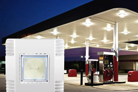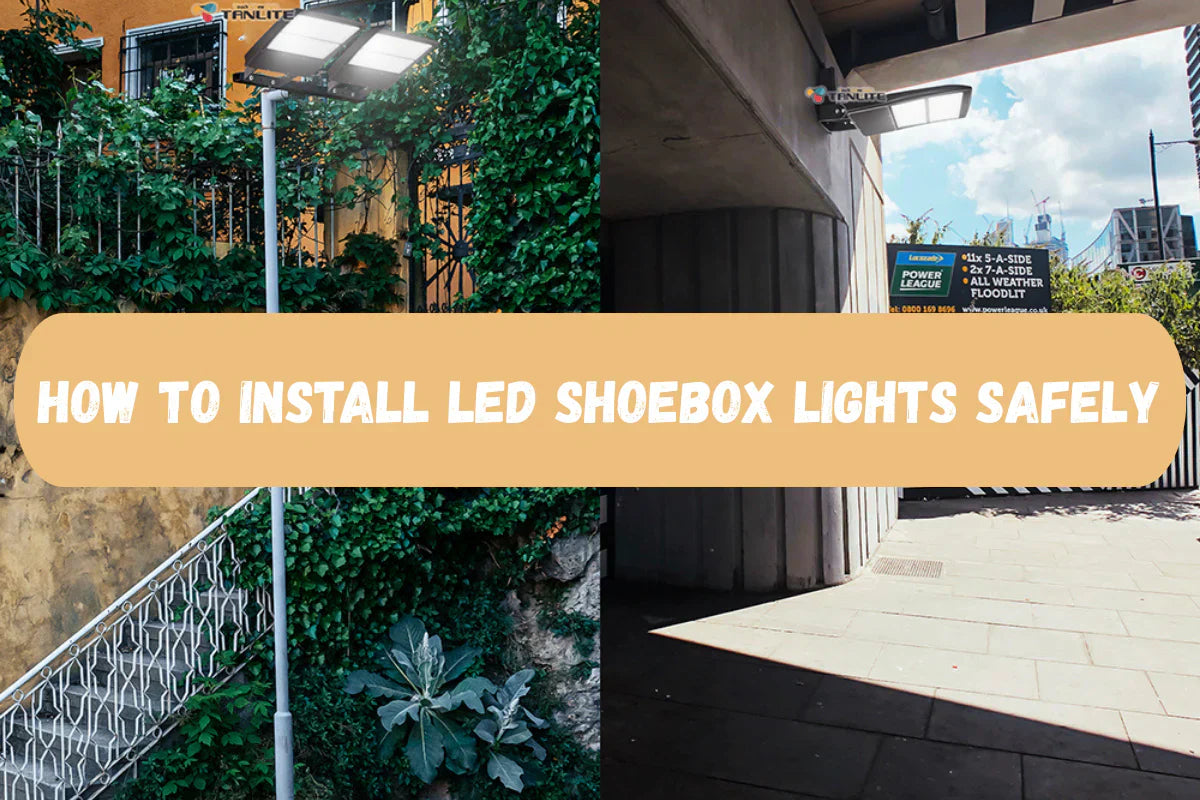
Upgrading your parking lot, roadway, or campus with LED shoebox lights improves safety, cuts energy, and reduces maintenance. This hands-on guide walks you through safe, code-compliant installation and wiring—tailored for contractors and facilities using LFD Lighting LED Parking Lot Lights. If you’re still selecting fixtures, explore LFD Lighting’s lineup here: LFD Lighting Shoebox Light
What you will need
- LFD Lighting LED shoebox fixture, mounting arm/slip fitter/yoke, and accessories (photocell, shorting cap, motion sensor as specified)
- Voltage-matched driver (e.g., 120–277V or 277–480V, verify on the driver label)
- Weather-rated conductors (THHN/THWN), wire connectors, and bonding hardware
- Hand tools, torque wrench, level/inclinometer, multimeter/non-contact voltage tester
- Outdoor-rated junction box or pole hand hole access, silicone gasket-safe sealant if specified
Step 1: Pre-checks before installation
- Confirm voltage: Match circuit voltage to the driver input printed on the fixture label.
- Check pole and arm: Confirm pole height, tenon/arm size, and EPA/wind rating are adequate for the fixture + arm + accessories.
- Inspect components: Verify the box includes the correct mount (slip fitter, direct/arm, or yoke), gaskets, hardware, and any controls ordered (photocell, NEMA receptacle, shorting cap).
- Plan optics and aiming: Most parking lots use Type III on perimeters and Type V in central areas to improve uniformity and minimize spill.
Step 2: Mounting the fixture
LFD Lighting shoebox lights are available with multiple mounting options to fit new and retrofit poles. Shop mounts and fixture options: LFD Lighting Shoebox Light
A) Slip fitter (on a tenon)
- Fitment: Most slip fitters accept a 2-3/8 inch (60 mm) O.D. tenon. Verify your tenon size.
- Prep: Feed conductors through the tenon or fitter per the manual. Ensure gaskets are seated.
- Place and align: Slide the slip fitter onto the tenon. Use a level to set zero tilt unless a design tilt is required. Avoid excessive tilt that increases uplight/glare.
- Tighten: Evenly torque the set bolts to the manufacturer’s spec. Bond the ground to the pole if required.
B) Direct/arm mount (square/round pole)
- Bracket: Attach the arm/bracket to the pole using the provided template and hardware. For round poles, use the correct adapter.
- Wire routing: Pull supply conductors through the pole hand hole into the arm cavity.
- Secure: Mount the fixture head to the arm. Level and torque all fasteners per spec.
C) Yoke mount (wall or surface)
- Anchors: Use appropriate outdoor anchors for the surface. Seal penetrations.
- Aim and secure: Set the aiming angle and torque the yoke bolts. Ensure drip loops on exposed conductors.
Step 3: Line-voltage wiring
Typical North American color codes are shown below; always follow the label in your specific LFD Lighting fixture and local code.
Function | Typical fixture lead color
- Line/hot (L) | Black or Brown
- Neutral (N) | White or Blue
- Ground (G) | Green or Green/Yellow
Wiring steps
- Verify power is off. Test for absence of voltage.
- Make up connections:
- Connect Line to the fixture’s Line lead.
- Connect Neutral to the fixture’s Neutral lead.
- Connect Ground to the fixture’s Ground lead and bond to the pole if required.
- Use outdoor-rated connectors and strain reliefs. Keep low-voltage control wires separate as required by code and the fixture manual.
- For 277–480V circuits: Only use fixtures marked and equipped for high-voltage input. Never connect 480V to a 120–277V driver.
- Close all compartments ensuring gaskets are not pinched.
Step 4: 0–10V dimming and controls
Many LFD Lighting shoebox models are controls-ready. See available options here: LFD Lighting Shoebox Light
-
0–10V dimming: The dimming leads are typically Purple (+) and Gray (–).
- If using a dimmer/control: Connect Purple to 0–10V + and Gray to 0–10V – from the controller. Keep polarity correct.
- If not using dimming: Cap each lead separately; do not tie them together. The fixture will run at full output.
-
Photocell (twist-lock): Install in the NEMA 3- or 7-pin receptacle if equipped.
- Orientation: Align the “NORTH” arrow on the photocell to true north for accurate day/night switching.
- Shorting cap: Use this to bypass the photocell (fixture controlled by the branch circuit or another controller).
- Motion sensor: If your model includes an integral sensor or remote head, connect per the wiring diagram and program on-time, high/low dim levels, and hold time as specified.
Step 5: Power-up and commissioning
- Restore power and verify each fixture turns on.
- Test controls:
-
- Cover the photocell to simulate night; uncover for day.
- Verify 0–10V dimming response and motion sensor programming.
- Check uniformity: Walk the site at night. Look for dark spots, glare, or spill. Adjust tilt if allowed by spec.
- Finalize: Record circuit numbers, fixture locations, and control groupings for maintenance logs.
FAQs
Q:Can I use existing poles?
A:Yes—verify pole height, condition, hand-hole access, tenon/arm compatibility, and EPA/wind ratings.
Q:Do I need a photocell if I have a timeclock or BMS?
A:No. Use a shorting cap on NEMA-equipped fixtures and let your controller switch/dim as needed.
Q:What wire gauge should I use?
A:Size conductors per code based on load, run length, voltage drop, and ambient conditions. Your electrician will calculate this.
Q:Can I dim without a control system?
A:Most 0–10V drivers require a controller to dim. Without one, cap Purple/Gray and the fixture runs at full output.
Need help with selection or a quick layout?
Send your site plan and mounting heights, and the LFD Lighting team can help you choose wattage, optics, mounts, and controls. In the meantime, browse and spec your fixtures here: LFD Lighting Shoebox Light